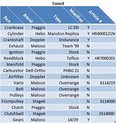
How to: Tune, port and rebuild a Piaggio engine to Mid-Race spec
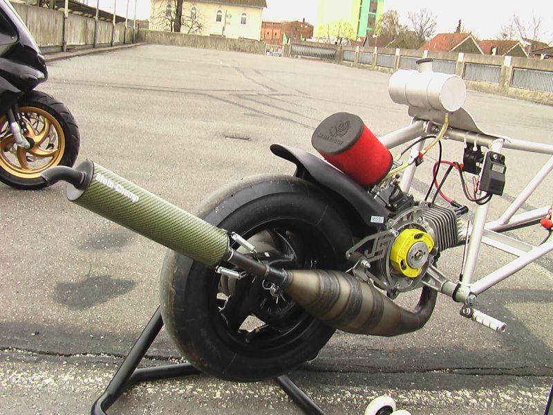
We all know that scooter tuning is not exactly the cheapest hobby you can choose. Given the average tuner age of 15 to 19 it is particularly hard to finance this hobby and most of us tend to tune in a step by step process. This can be done for certain parts but especially the engine should be seen as a single component where every part needs to match the other to work as expected. This post will explain the tuning process of a Piaggio engine I did for one of my friends back in 2010. He rode his scooter (Gilera Runner) on a daily basis and thus the goal was to create a well performing street race setup that is reliable and affordable.
The Start
Although he already had a respectable daily driver setup, he asked if I could take a “look”. The engine was already well tuned and he had a lot of fun riding it. Unfortunately he had some electric problems with his ignition. He bought another scooter with a minimal setup (70cc DR) to ride to work and asked me to upgrade his Runner.
Back in 2010 his setup was:
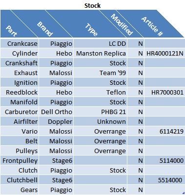
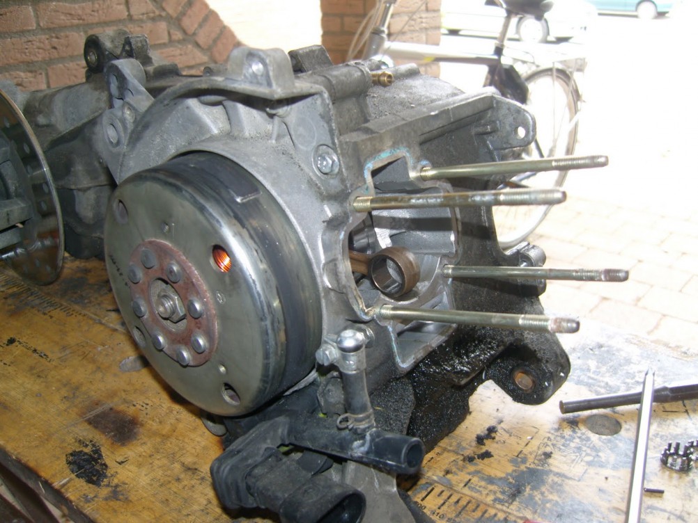
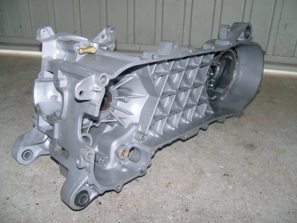
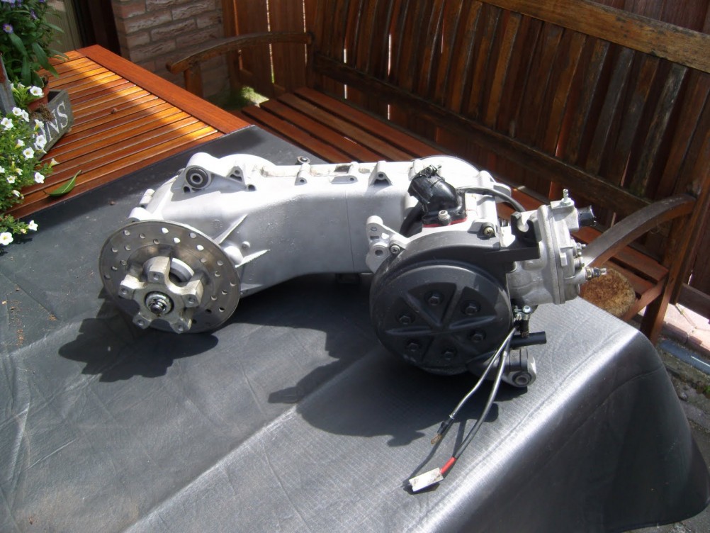
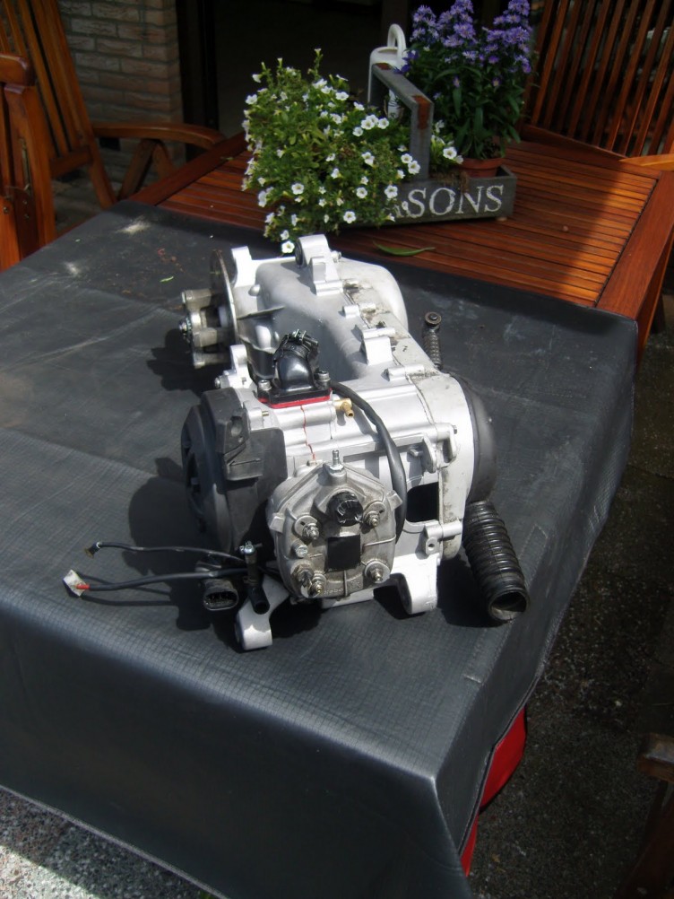
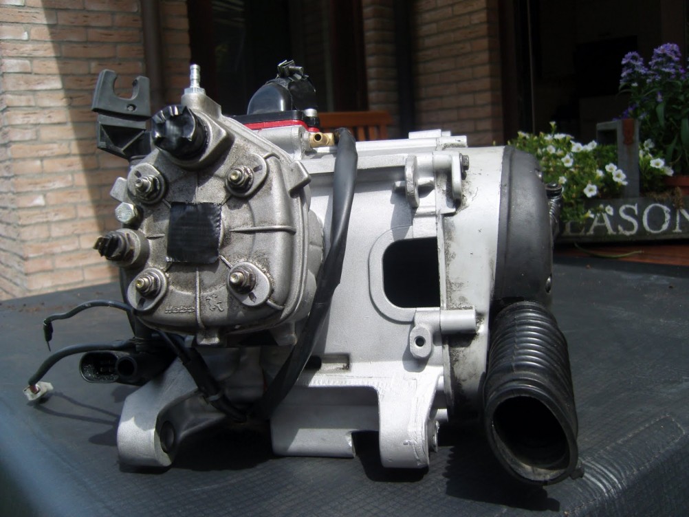
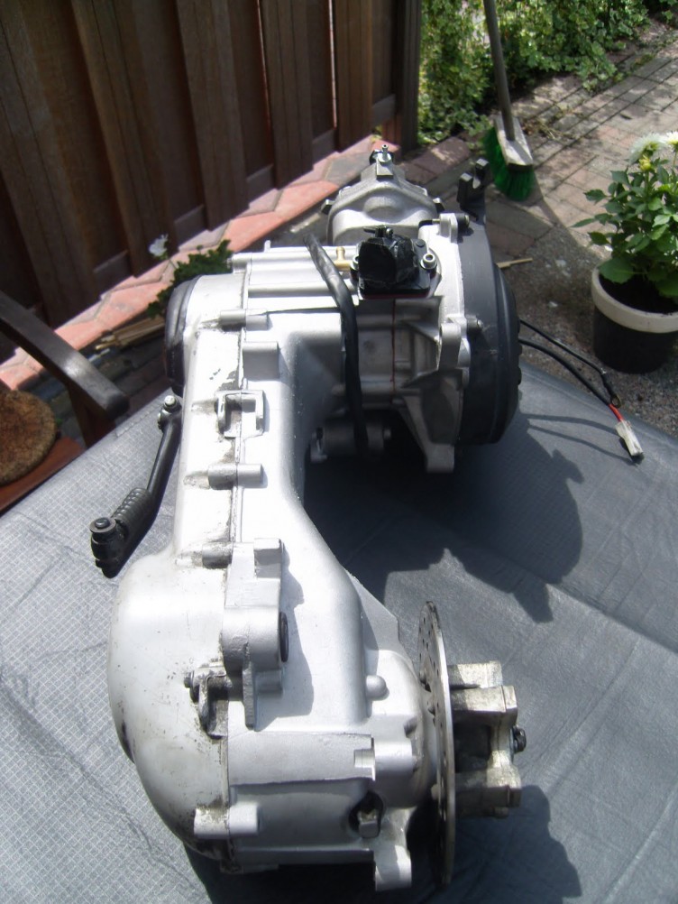
Splitting the Engine
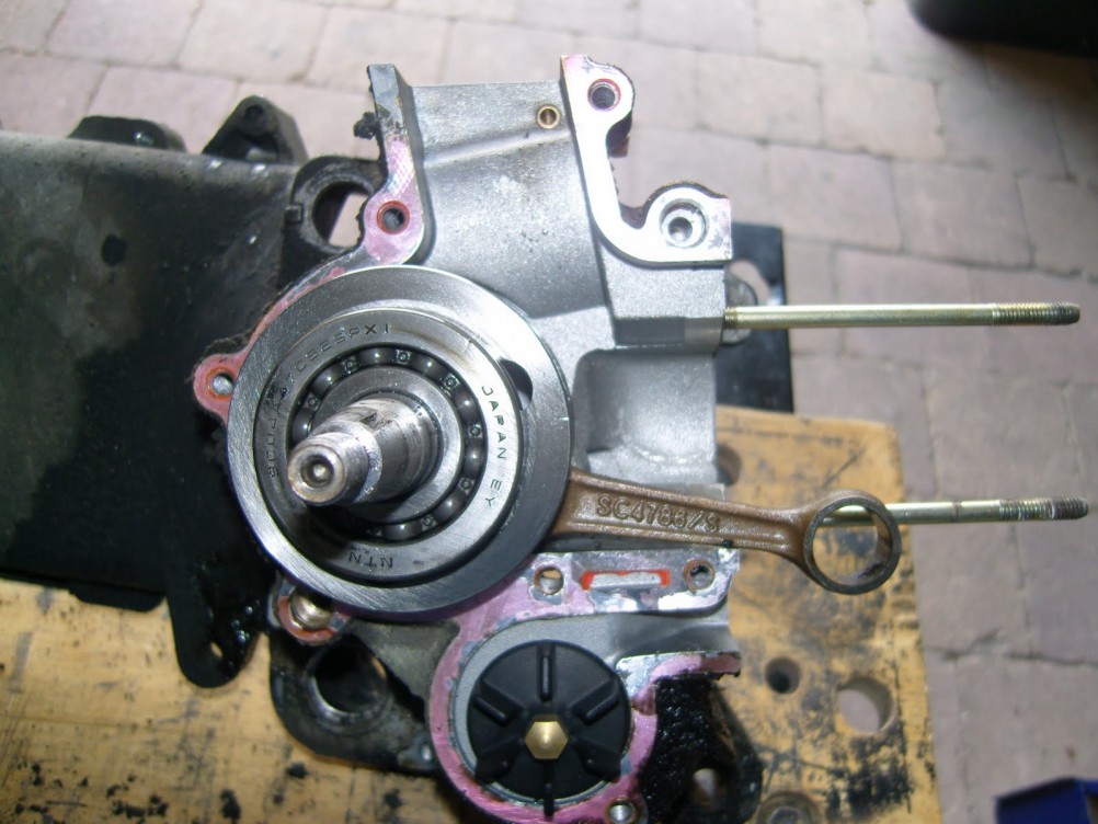
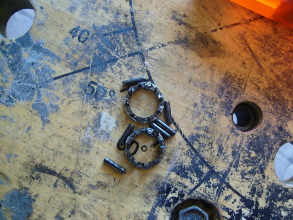 Destroyed Needle Bearing
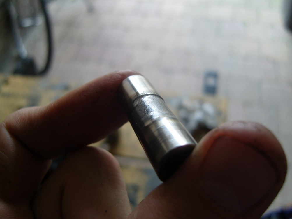 Overheated Gudegeon Pin
I started dismantling the engine for cleaning, tuning and rebuilding. When I took off the cylinder I made a somewhat unpleasant discovery… The piston needle bearing was in pieces and ate away material from the piston pen. These are the things you don’t want to encounter when removing a cylinder.
The piston pen is made of hardened steel and you need a lot of and friction to make it look like on the pictures. This gives a good idea of the amount of force the piston is blown down with on ignition! Therefore it is important to use the right bearings and high quality parts when building a performance engine.The good news though was that the cylinder wasn’t damaged at all! It was actually in a pretty good condition, a sign that it ran with enough oil and got maintained properly.
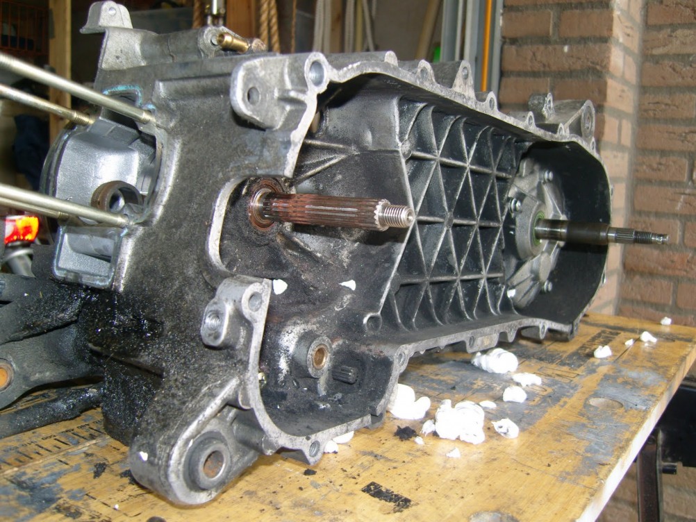
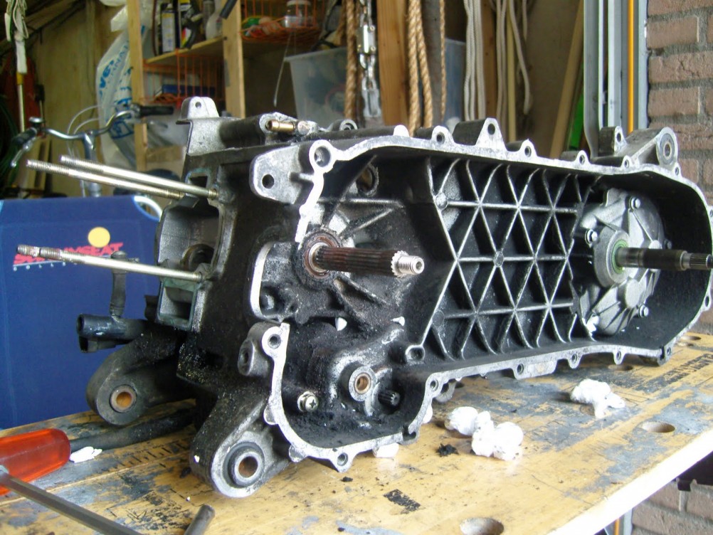
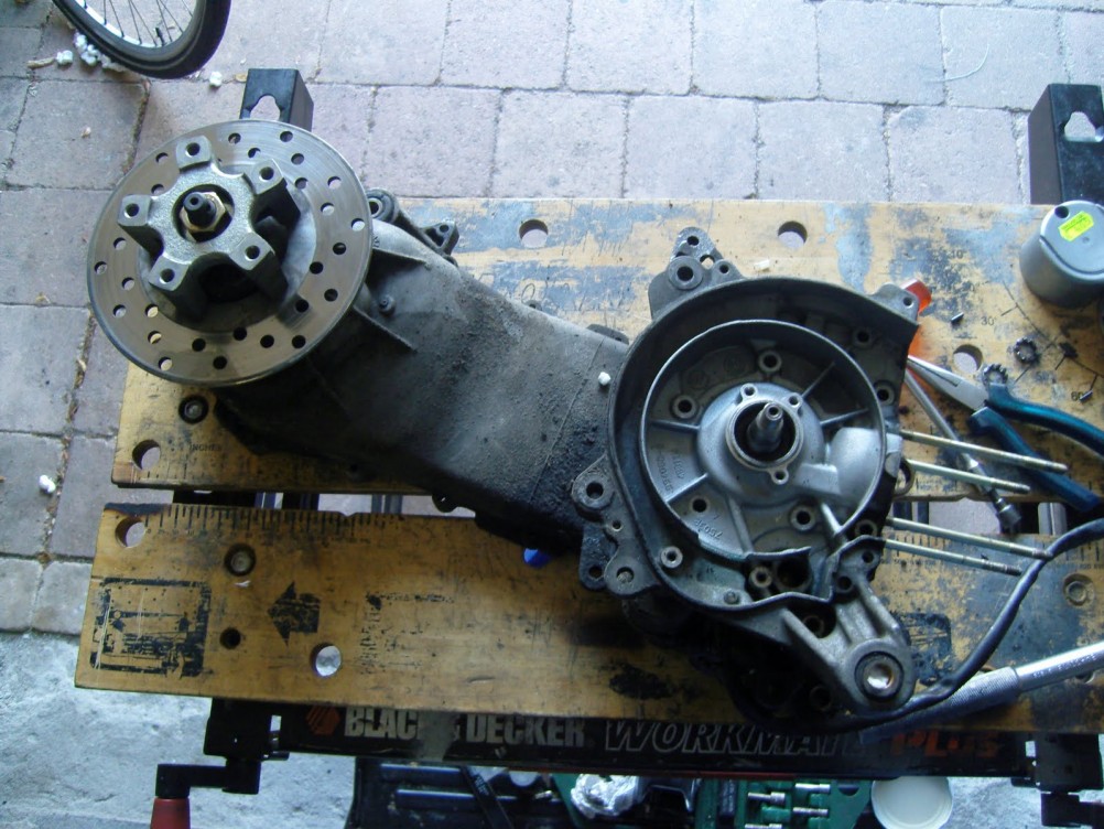
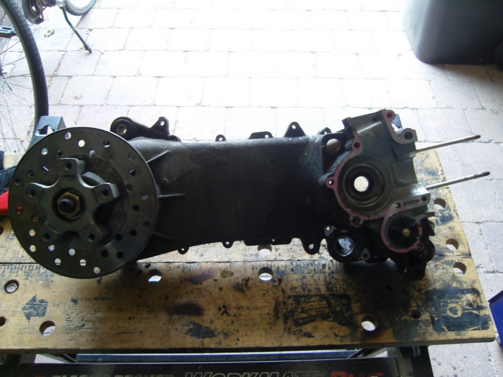
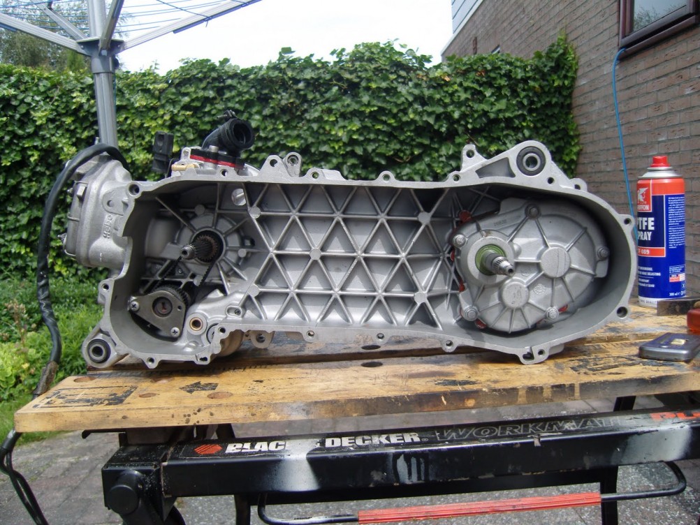
Part by part I dismantled the engine, until I was left with only an empty crankcase.
Tuning and Porting the Cylinder
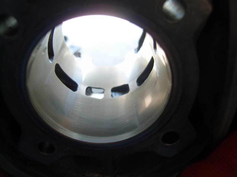
Next step was to tune the cylinder. Tuning a 2 stroke cylinder is done by changing port timings and increasing the port area. If done right, the engine will burn fuel more optimal, giving you a bigger bang and therefore more fun ;)
Before you can start milling, you should do some measurements and calculations. First you measure the timing of the cylinder. This can be done in several ways. You can either measure timing with a degree wheel or you can measure timings by measuring the distance between the top of a port and the top of the barrel. The distance can then be used to calculate degrees. I prefer measuring the distance using a caliper. There is no good or bad way of measuring timing. It all comes down to being precise. I use an excel spreadsheet where I enter the numbers in mm and it returns the degrees. There will be a dedicated article about this topic available on ultimate-tuning.de soon.
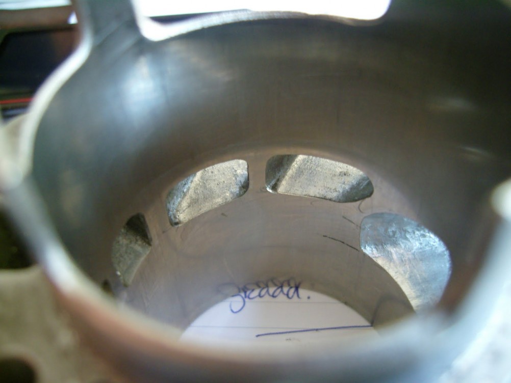
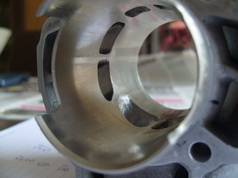
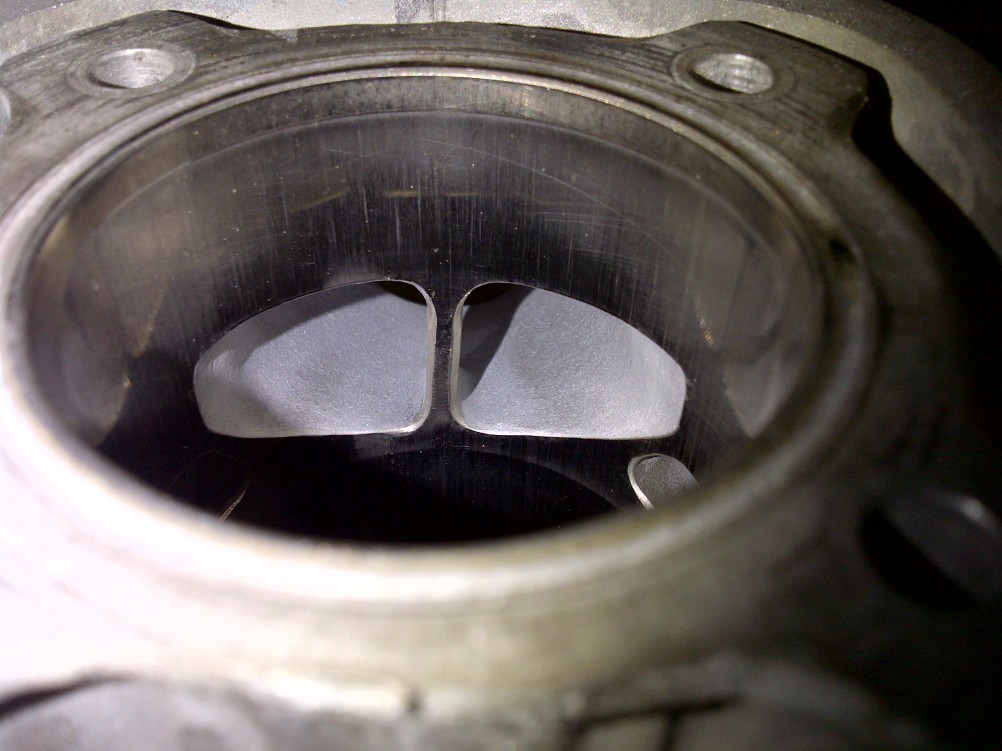
The transfers of the Manston Replica are equal to the real Manston cylinder, meaning a timing of around 130 degrees and good use of the cylinder surface. The primary transfers are "pulled" towards the exhaust port and the secondary transfers are close to the boostports (at the back of the cylinder). The part that makes this cylinder rather tame is the exhaustport. It's relatively small and it has a low timing (185 degrees). Luckily, there is enough material that can be removed. It could even be upgraded to Manston level, but that was not what I wanted as my friend still wanted to be able to use his scooter every day. So there was no need to go all the way.
After doing the math, it was time to mark the right distances and started milling.
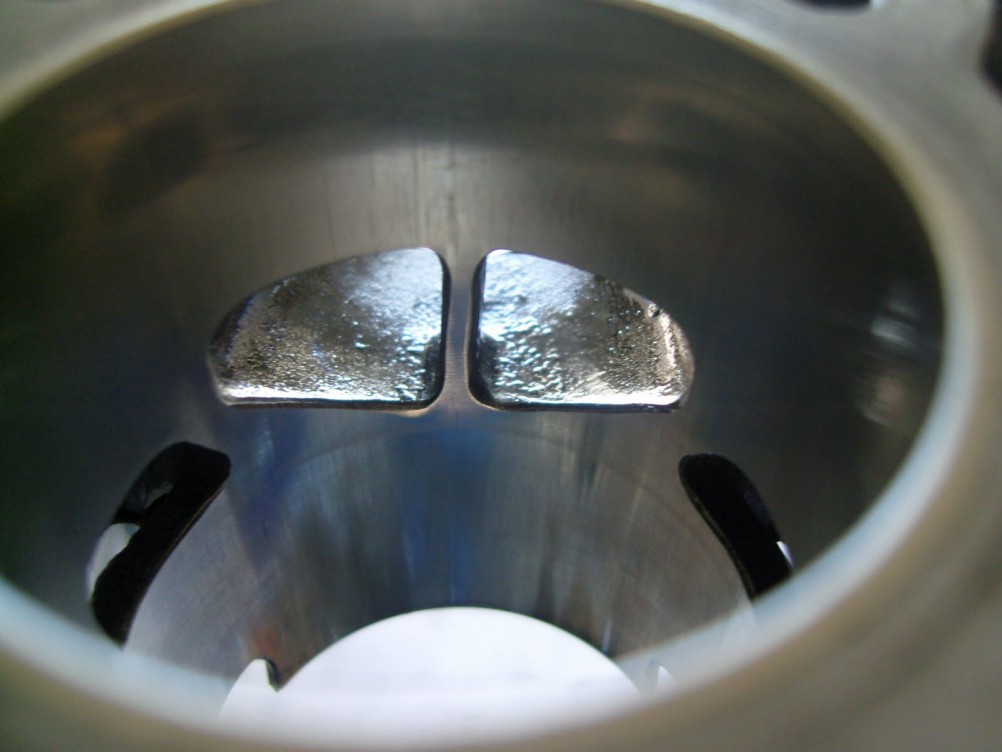
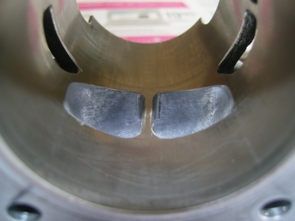
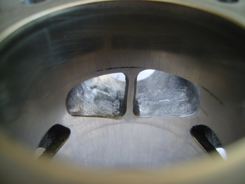 Exhaust port was marked and raised
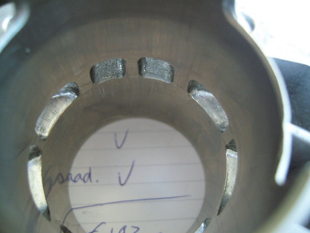
 Ports were slightly polished
I did some more cleaning up and this was the end result:
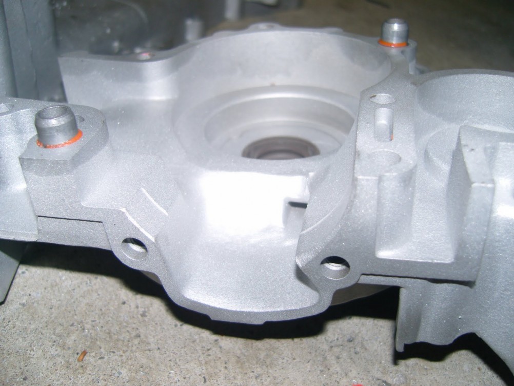
Flowing the Engine Case
Tuning a cylinder is a great way of gaining performance, but it isn't the only part that can be tuned. To unleash full power of any setup you have to make sure things match. The transfer tunnels on the cylinder are wider than the tunnels on the crankcase and therefore disrupting the flow to the cylinder. The next step was to tune the crankcase so the mixture can flow right into the cylinder.
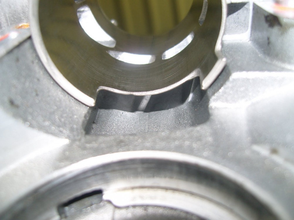
Tuning a crankcase isn't that hard. It is important that you work precisely (the more precise, the better the result!) and do not remove too much material as some parts of the crankcase are thinner than others (if you accidentally take off too much you don't need to worry, as some 2 component aluminum from the local home center will fix it).
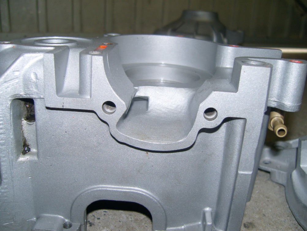
A good way to start is by placing the foot gasket over the cylinder studs and mark the difference. I would not cut away all the material that was marked, because gasket and cylinder don't match 100%. So stop before you reach the end of the marked part. If you have reached the markings slide the cylinder over the studs and see how far you have to go and where it might need some more adjustments.
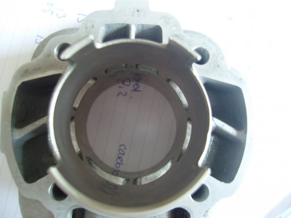
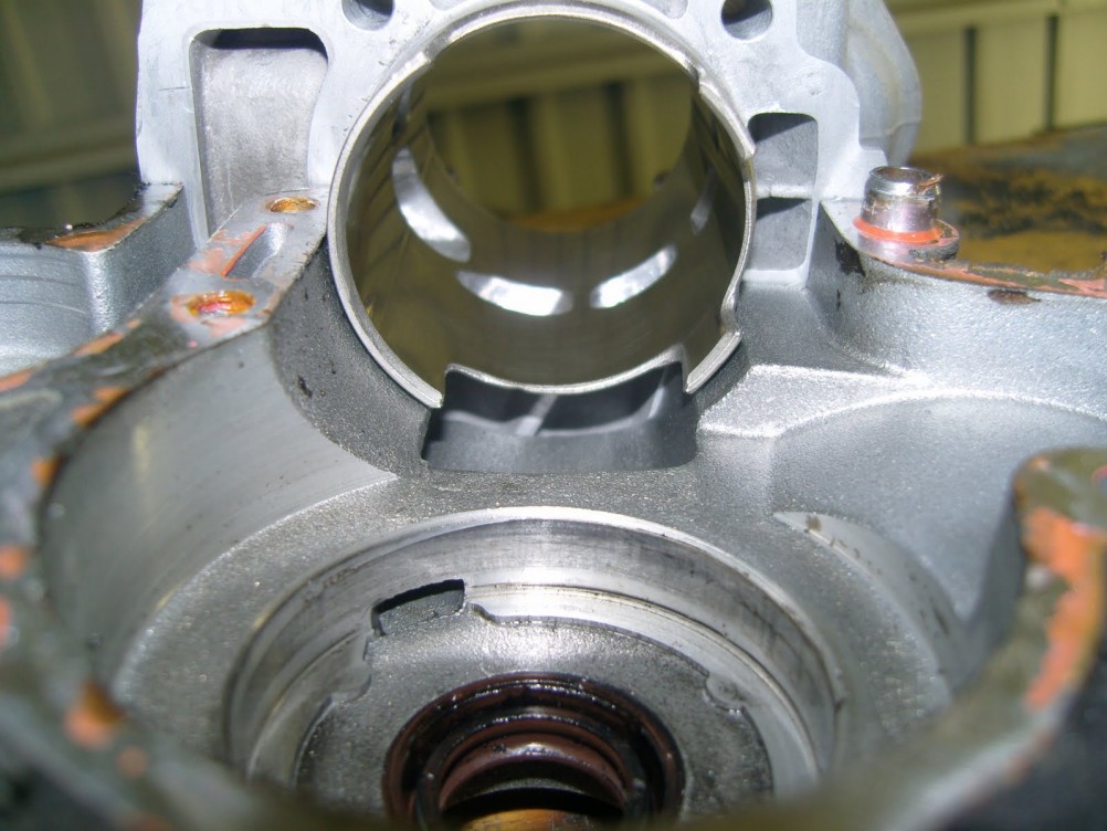
After some milling it should look like this:
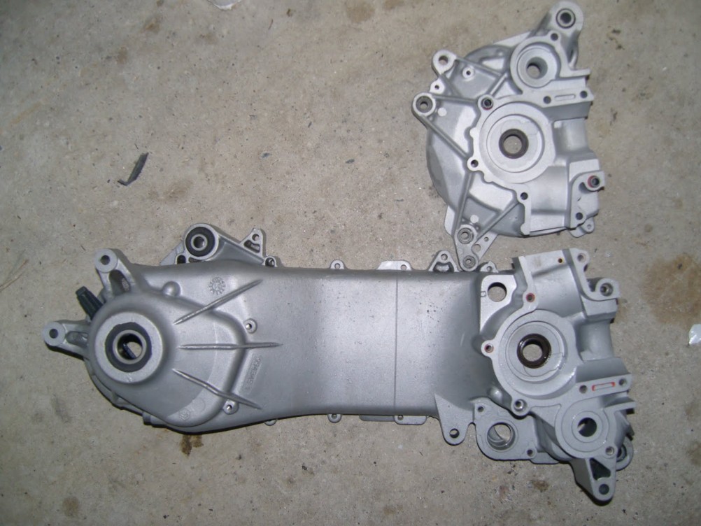
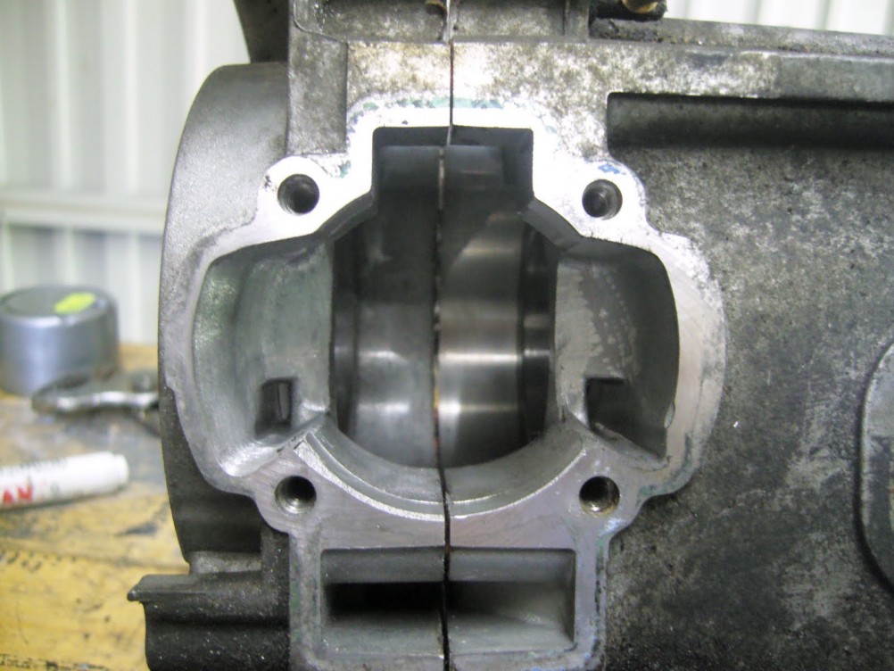 Side by side comparison of a tuned engine case and a non-tuned one
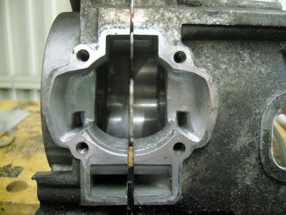
Cleaning the Engine
Before I rebuilt the engine, it needed cleaning. I sandblasted the crankcase so it would look brand new again.
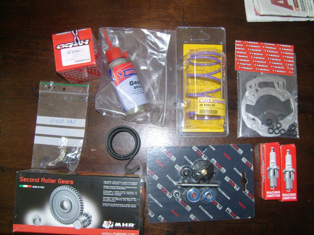
In the meantime, I ordered a new crankshaft (Doppler), Malossi primary gears and some small parts like a new water pump kit, gaskets, sparkplugs, etc. If you are rebuilding, do it properly!
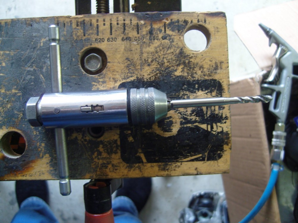
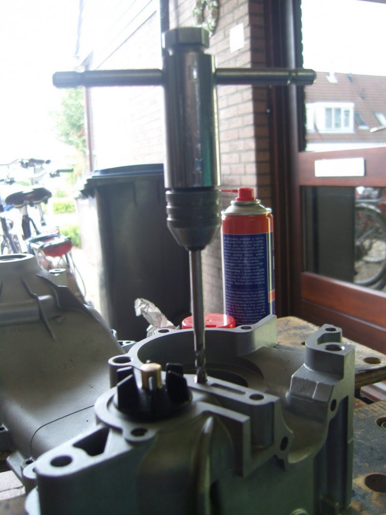
Before mounting back all the parts, the crankcase was cleaned so all sand was removed (sand and engine parts is no good) and the threads of all screw holes were tapped clean. If you don't do this you could damage the screw hole threads when screwing in the bolts. Besides this it also makes it easier to turn in the bolts, as there is no more sand and dirt in the holes.
Assembling the Engine
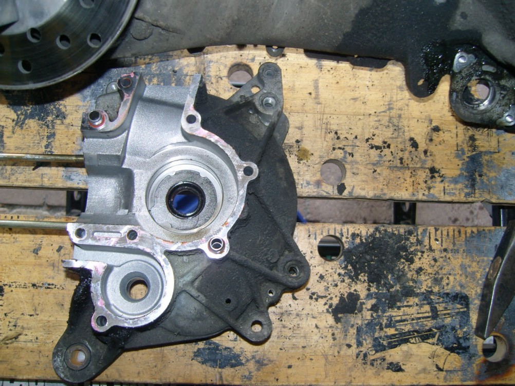
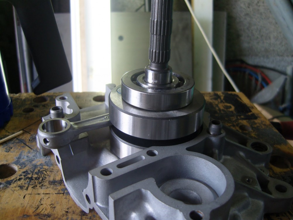
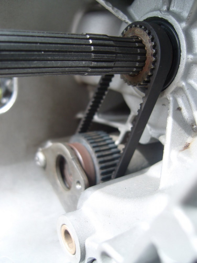
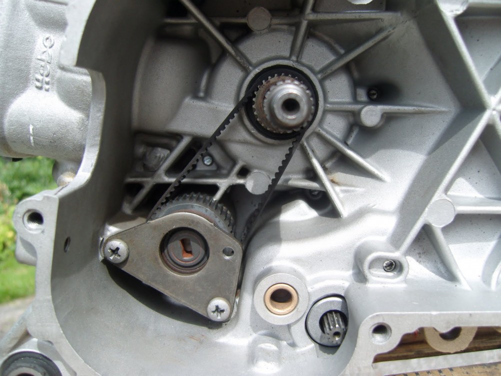
After this was done I installed the waterpump and the crank. Mounting a crankshaft can be done in several ways. I prefer to have the bearings on the crank before I mount the crankshaft in the crankcase.
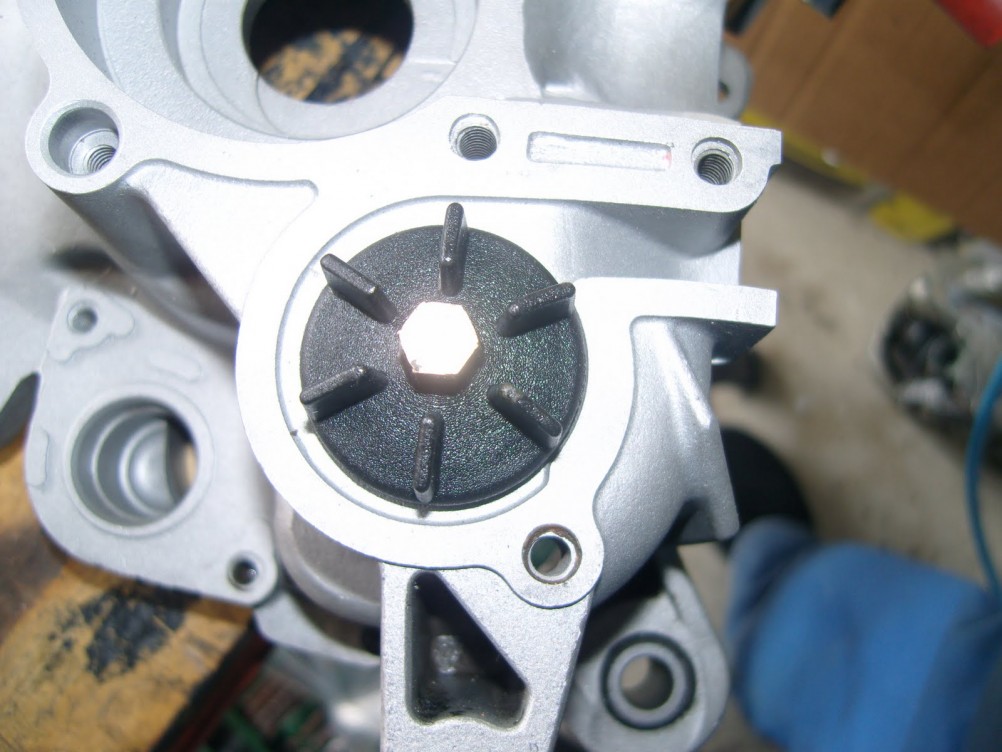 Water pump wheel
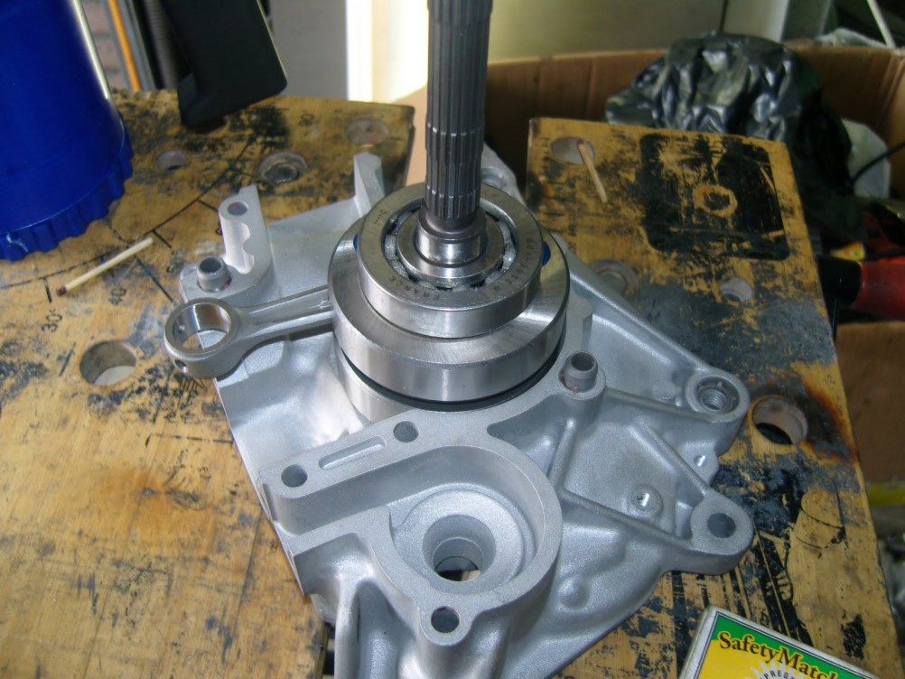
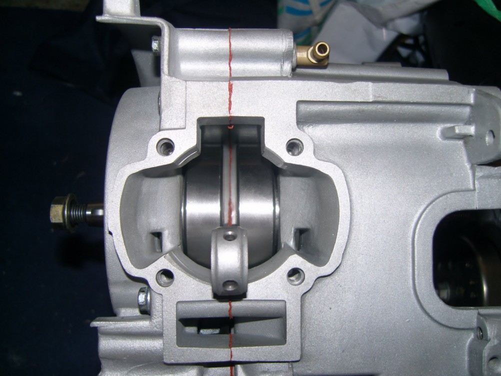
I pressed in the new Malossi gears (14/39 ratio) and mounted them into the case.
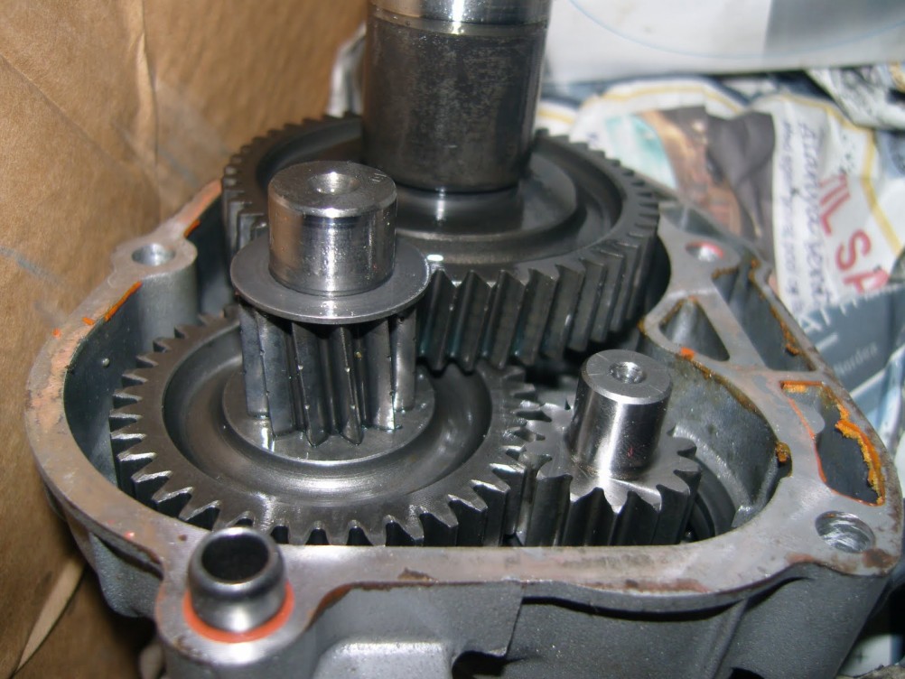
As you can see on the picture above, the cylinder and waterpump were mounted too. Because the original oil pump is not suited for this rpm, I removed it. To make sure that the waterpump wheel wouldn't slide off its shaft I used an old crankshaft seal that fits right over it.
The cylinder was mounted and torqued down with 11nm on all four studs. The way to do this is cross ways so that all force is distributed equally. Not doing this will lead to extra friction, giving more wear on piston and ring.
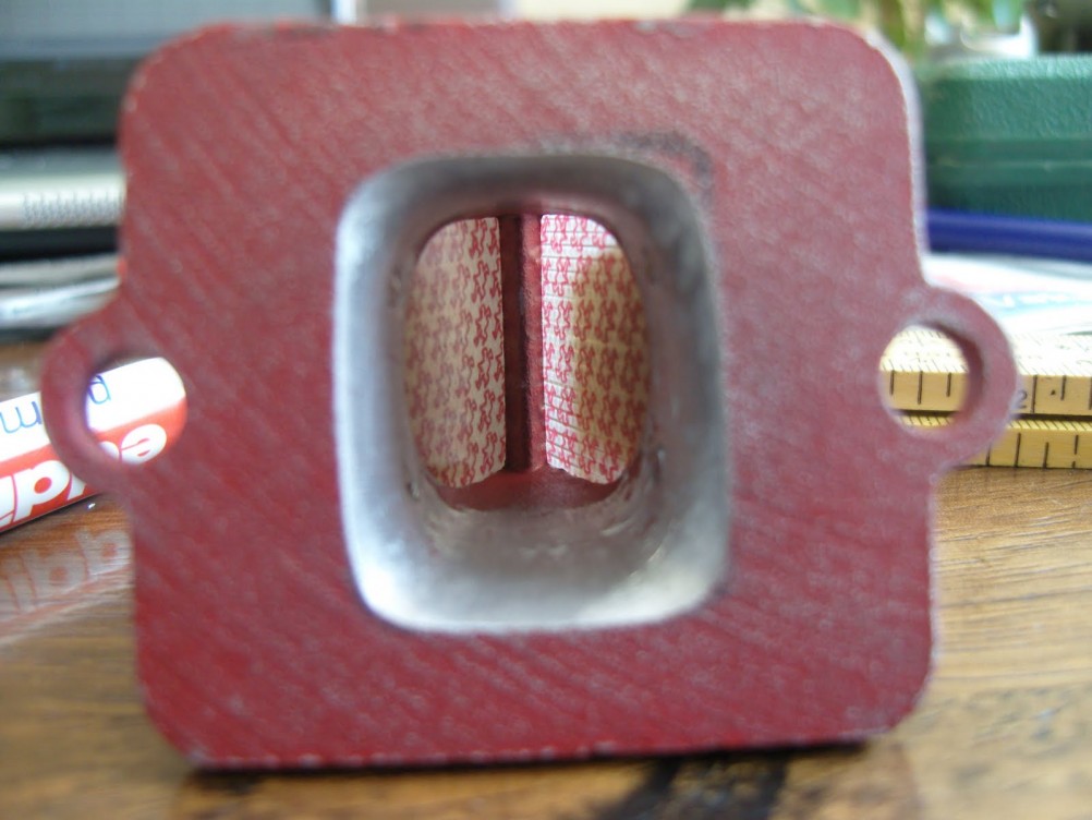
Tuning the Reed Valve Block
When I was going to mount the reedblock and manifold back, I noticed that those didn't match. The opening of the reed valve block and the manifold differed in shape and size.
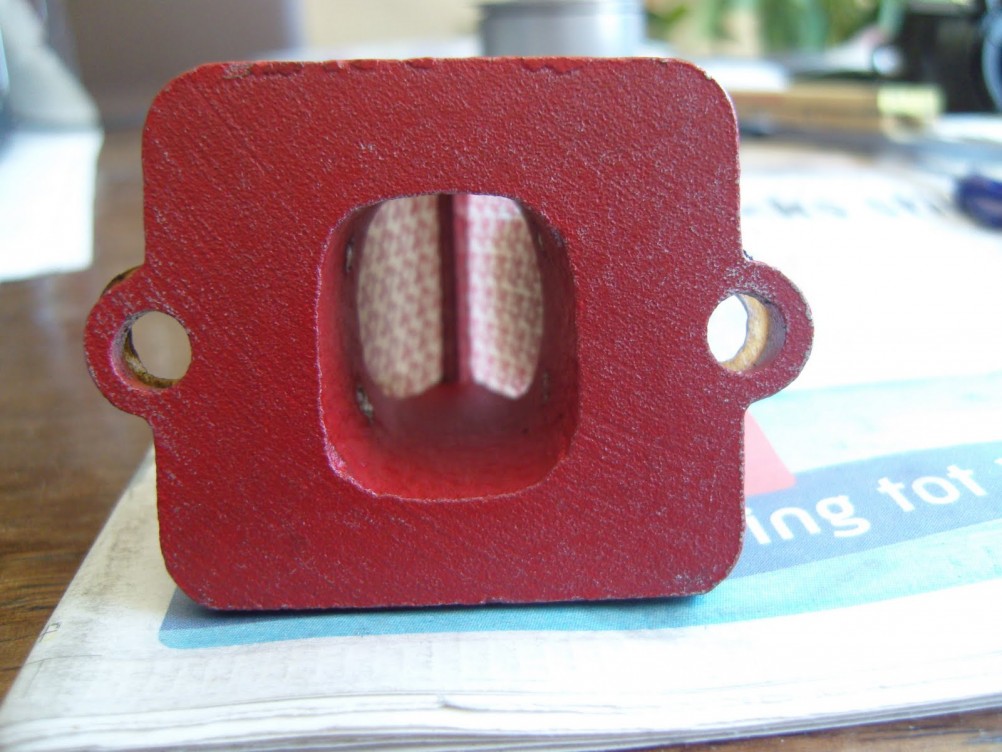
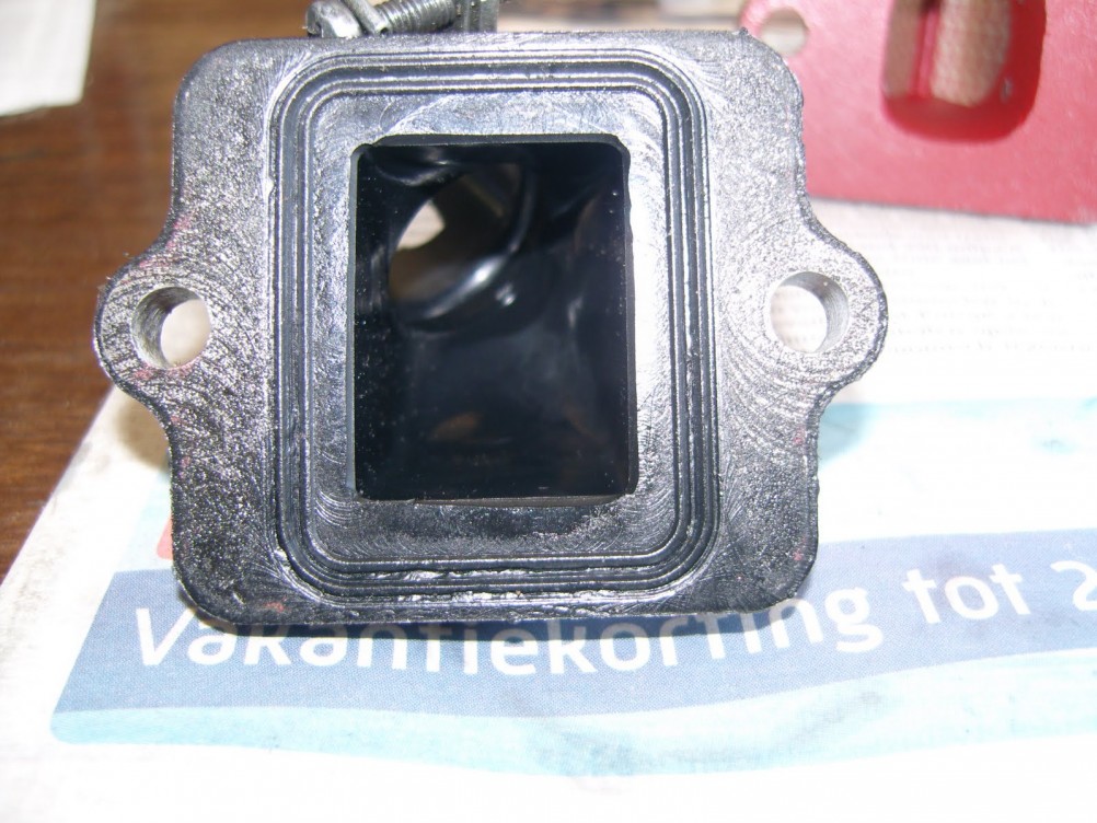
Nothing I couldn't fix, so I took my rotary tool and altered the reed valve block.
After that it finished mounting all the parts, so it could be returned to my buddy.
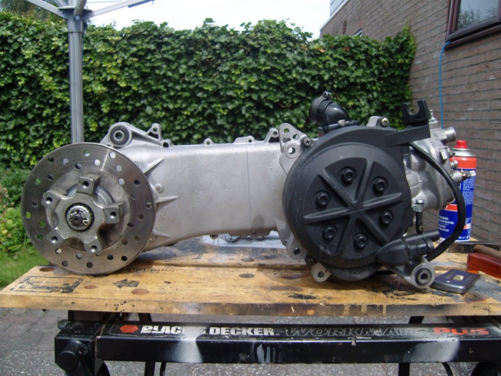
The engine was shipped back to my friend and he was amazed by the performance gain. He still uses the engine every day, without any problems. I personally found it fun to work on this engine and it makes me proud that it is being used every day. I don't know how much HP this engine has, since it was not tested on a dynometer bench. However, I did drive it and if I was ask to given an estimate of power I would say it should be somewhere around 18 RWHP. Not too bad for a Manston Replica!
The Final Setup
Update 2012:
As I wrote at the beginning of this post, my friend bought another scooter as a daily driver and we decided that the engine could use an update. The work on this engine is still ongoing but the cylinder already got some more exhaust port area and the ports got cleaned up. The port timings won't be increased since the Malossi Team 99 exhaust needs to be used. We will also modify the exhaust flange for the cylinder with a straight instead of an angled one (I expect that to give about 0.3 - 0.5 hp more) and the scooter will be set up on a dyno for maximum performance. The crankcase will remain stock, but cleaned and the gear and wheel bearings will be replaced with new fresh bearings.
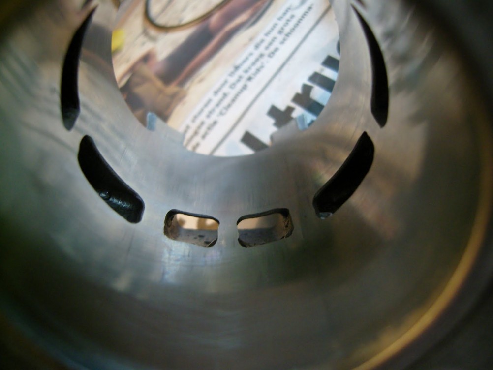
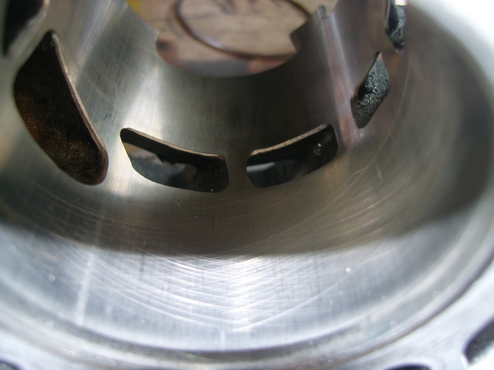
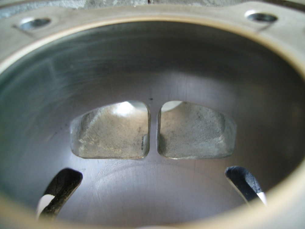
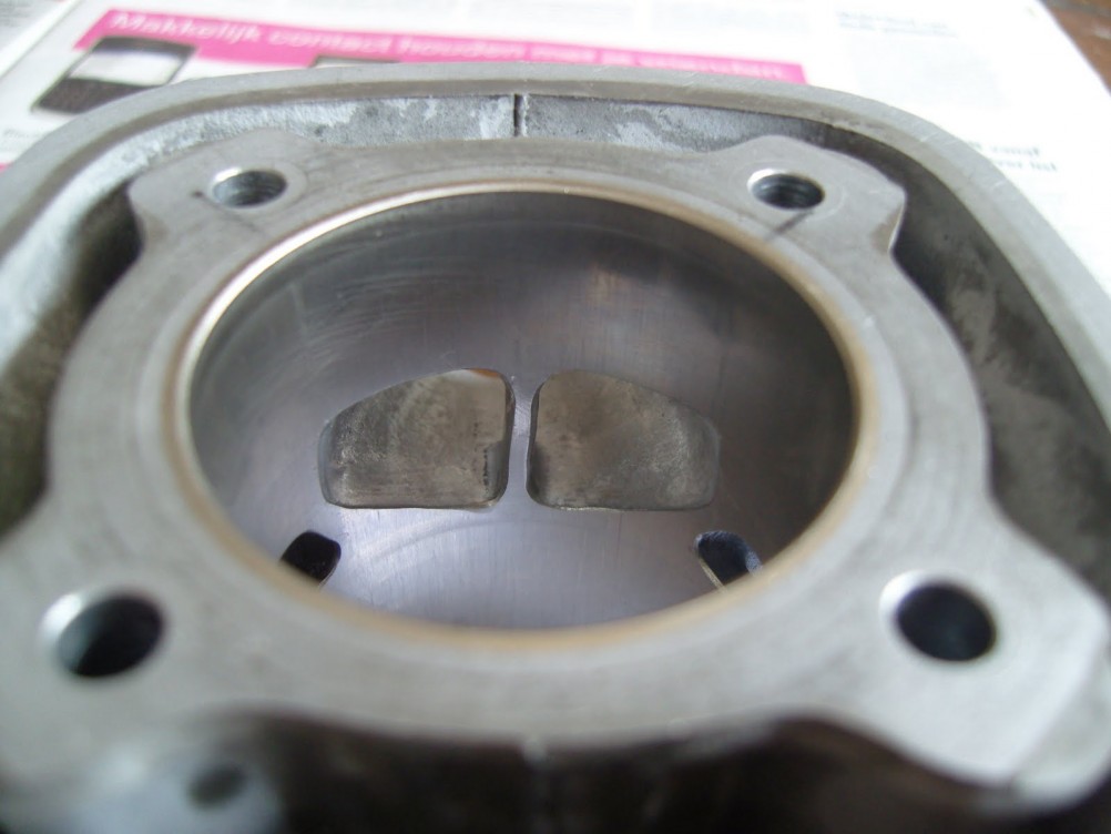
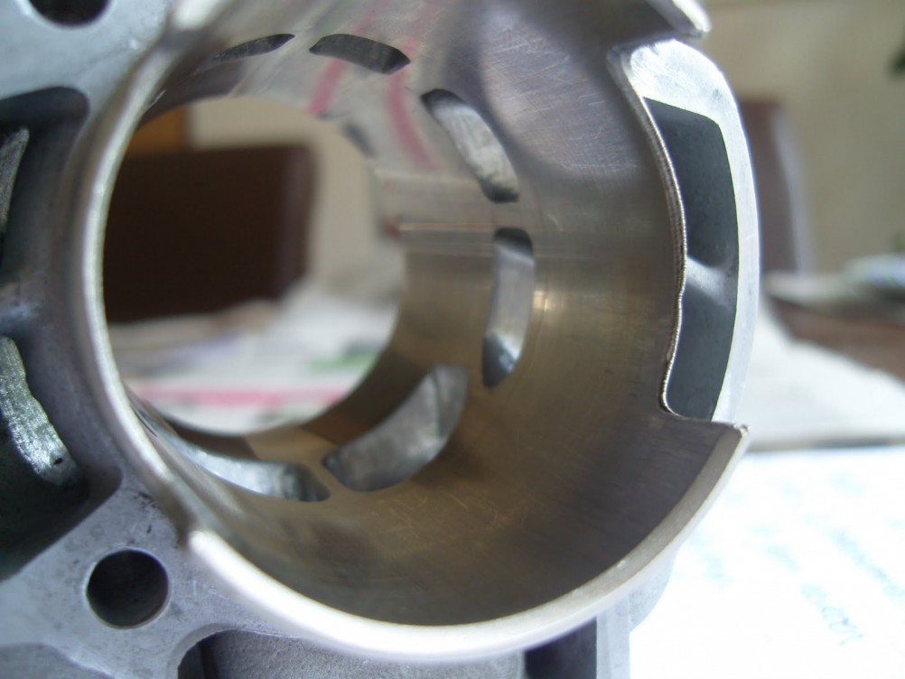
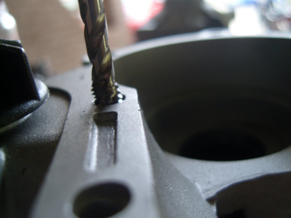
Here is a picture of the cylinder:
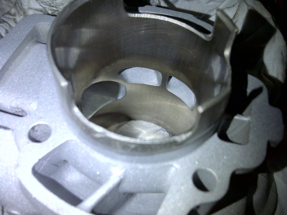
You can see the exhaust port has been increased. I cleaned it up by sand blasting the cylinder (masking the cylinder wall). This gives a smooth finish and makes sure that all surfaces are clean for good seal between the cylinder and the crankcase. Before mounting the cylinder we might consider giving the cylinder a hone job, removing a thin layer of nicasil. This will ensure that the cylinder is 100% round and that the oil will "stick to the wall".
Below we have a picture of pressing out the wheel bearing. That needed replacing since it had quite some play on it.
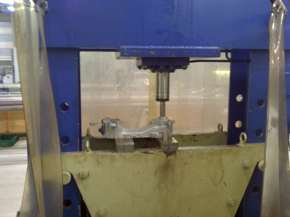
New bearings have been already bought. In the coming weeks I will mount these bearings and reassemble the engine. What is left is to design an exhaust flange that matches the cylinder and will improve the performance of the exhaust. I will keep you updated.
I hope you enjoyed reading this.
Stay tuned for more!
Bram
23 Comments
I am very interested in your article i drive a zip sp with a dr70 tuned.
And i would like to tune the engine more.
But the most picture's in your article don't work.
which is kind of sand, did you use to sandblast the Engine blok,
fine / medium or corse ?
Actually what you should use are glass pearls. Sand is bad!
Luke
where can i take it in london?
congratulations on your precision work.
My son diassembled completely the Ciao. Do you have instructions on how to reassemble the wires ? Thank you.
Am not so clearly understand when u altered the engine Crank. May I know how thinkness of the alterations? Sp 180
I am building project.
Thanks
It is very easy even for noobs, if you are interested
simply search in gooogle: pandatsor's tools
just had to install a new crankshaft in a liberty 50,
this was a great help :)
I have a Piaggio zip50 4t scooter. I Live in Cuba and here is very difficult to find parts, I would like to know if there is any upgrades kits like MGH423 that fits hiPER4 engine. Almost everything available here is for GY6 engines and I' m not sure if they can be matched. Any help on these would be really appreciated.
I want to upgrade from 50cc to 80 or perhaps 100cc so besides valves and cylinder kits what else should I take into account?
Sorry for my english, is not my native language.
best regards,
Amado